Electrical duty
Nominal voltage, operating window, continuous current, peak duration, runtime and charging method must agree.
OEM / ODM battery engineering
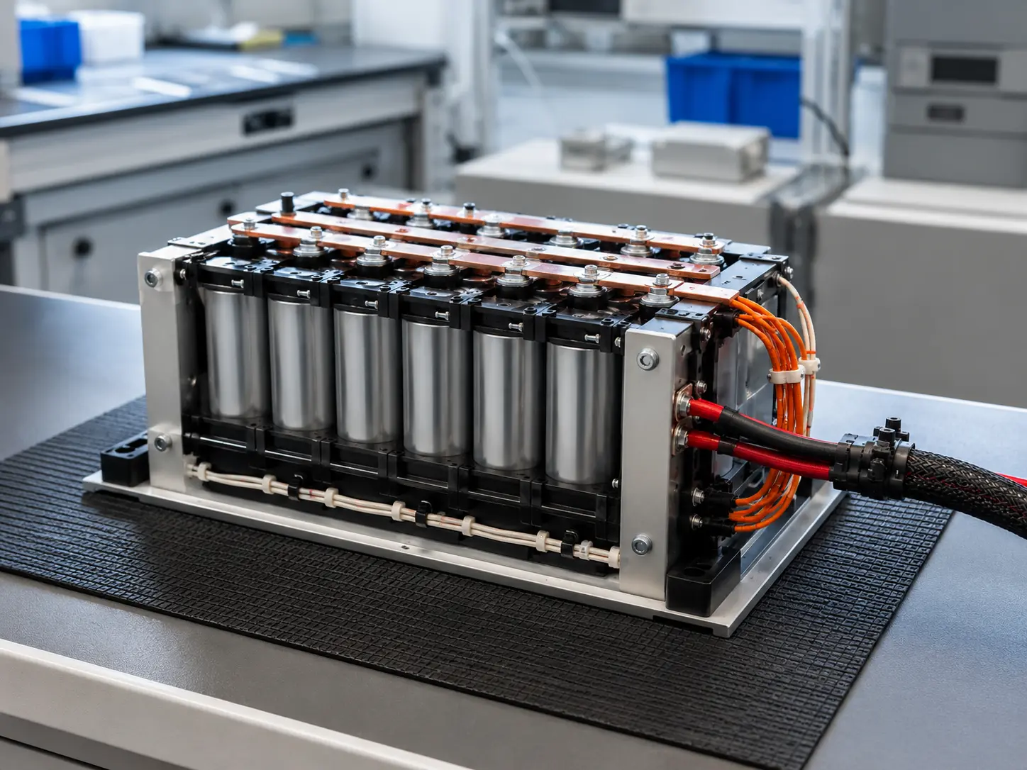
A structured development path from application requirements and cell qualification through electrical architecture, BMS, mechanical integration, interfaces, testing and supply planning.
Application first
The pack must support the real load while fitting the product, communicating with the host, remaining serviceable and following the intended compliance path. The development scope begins by closing those interfaces.
Nominal voltage, operating window, continuous current, peak duration, runtime and charging method must agree.
Space, orientation, mounting, connectors, cable exits, impact, ingress and thermal context shape the architecture.
BMS functions, sensing, balancing, communication and host-control responsibilities must be defined.
Prototype quantity, validation responsibility, certification, annual demand and change control affect development planning.
Engineering pathway
The pack is developed through controlled gates so that electrical, mechanical and commercial decisions remain traceable as the project matures.
Define equipment duty, load, charging, environment, space, interfaces, compliance and quantity.
OUTPUTPack requirement profileReview cell evidence and develop the series/parallel architecture against current and runtime needs.
OUTPUTCell/topology directionCoordinate BMS, protection, enclosure, connectors, communication and thermal conditions.
OUTPUTPreliminary pack designAgree prototype scope, tests, acceptance criteria, documentation and production transition.
OUTPUTDevelopment and supply planApplication fit
Application labels are starting points, not automatic product approvals. Final suitability follows the actual operating envelope.
Application-specific power for machines, controls and mobile industrial systems.
Battery packs shaped by peak current, duty cycle, charging access and communication.
Systems requiring coordinated enclosure, connector and environmental decisions.
Defined standby, readiness, runtime and host-interface requirements.
Projects where packaging, mass, current and mechanical retention must be balanced.
Custom modules or packs intended for integration into a larger branded system.
Evidence & decision boundary
Cell documents, sample measurements, BMS settings, pack architecture and application tests are not interchangeable. Each performance statement must identify which level was evaluated and under what conditions.
Review evidence governance →Prepare your RFQ
Share the known values and mark anything still undecided. We use these inputs to identify missing evidence, integration risks and the most practical next step.
Submit Project RequirementsTechnical FAQ
These answers establish the review process. Product specifications and commercial terms require project confirmation.
Provide the application, voltage range, runtime, continuous and peak current, charging method, available space, environment, interfaces, compliance needs and quantity.
Yes, subject to cell qualification and review of the electrical topology, current, enclosure, BMS, interfaces and project requirements.
BMS selection and integration can be part of the project. Required protection, sensing, balancing, communication and host-control responsibilities must be defined.
An existing pack can be used as a dimensional or interface reference, but chemistry, voltage behavior, charging, protection and compliance must be re-evaluated rather than copied blindly.
Prototype and production quantities depend on cell availability, engineering scope, tooling, compliance and supply planning. Submit the expected sample and annual quantities for review.
The compliance pathway can be planned with the pack project. Applicable standards, test responsibility, target markets and final configuration must be confirmed first.
Engineering inquiry
We will define the cell, architecture, interfaces and qualification questions needed to move toward a custom pack proposal.